Construction drawings explained: 10 essential documents architects should know
Discover the essential construction drawings every architect and designer must know. From site plans to millwork details, learn how each document helps bring your design vision to life efficiently and accurately.

Construction drawings are the backbone of any architectural project. These detailed documents guide the entire construction process, ensuring that the architect’s vision is brought to life accurately and safely. Whether you're an architect, designer, contractor, or engineer, understanding the different types of construction drawings is essential.
In this guide, we’ll break down the most important types of construction drawings, explaining what they are, what they should include, and who is responsible for creating them. We’ll also provide technical and design recommendations to help you make the most of each type of drawing.
What are construction drawings?
Construction drawings are a set of technical documents that detail the design, layout, and specifications of a building project. These drawings serve as a roadmap for contractors, helping them understand exactly how to execute the architect’s vision. They are legally binding and form part of the contract between the project owner and the contractor.
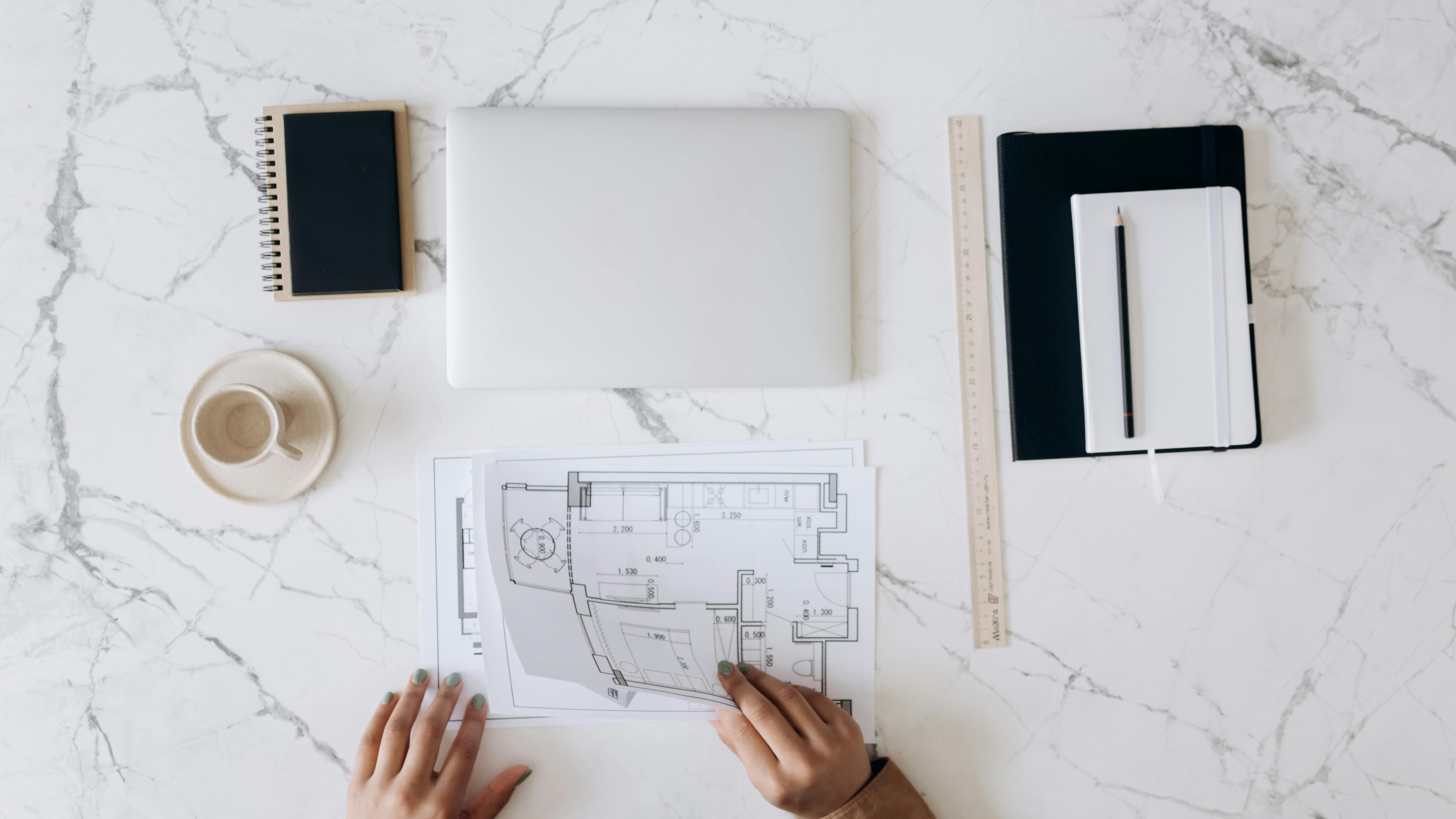
Construction drawings include everything from floor plans and elevations to structural drawings and MEP (Mechanical, Electrical, and Plumbing) systems. These detailed blueprints ensure compliance with building codes, safety standards, and the overall architectural intent.
Who creates construction drawings?
Several professionals collaborate to produce construction drawings, each contributing their expertise to different aspects of the project. Here are the key contributors:
- Architects: Responsible for the overall design and layout of the building, including floor plans, elevations, and sections drawings. They ensure that the building meets the client's aesthetic and functional needs while complying with local regulations.
- Structural engineers: Focus on the stability and strength of the building. They produce structural construction drawings that detail the framework, foundations, and load-bearing elements like beams, columns, and footings.
- MEP engineers: Mechanical, Electrical, and Plumbing engineers create the MEP construction drawings, which cover the building’s infrastructure systems, including HVAC, electrical wiring, and plumbing.
- Contractors/subcontractors: Often produce shop drawings for custom components and as-built drawings to reflect any changes made during construction.
- Civil engineers: Responsible for site plans and landscape architecture, ensuring the building is properly integrated into the surrounding environment.

Each professional works in tandem to ensure that every aspect of the design is covered and that the project is executed accurately and efficiently.
What are the different types of construction drawings?
1. Site Plans
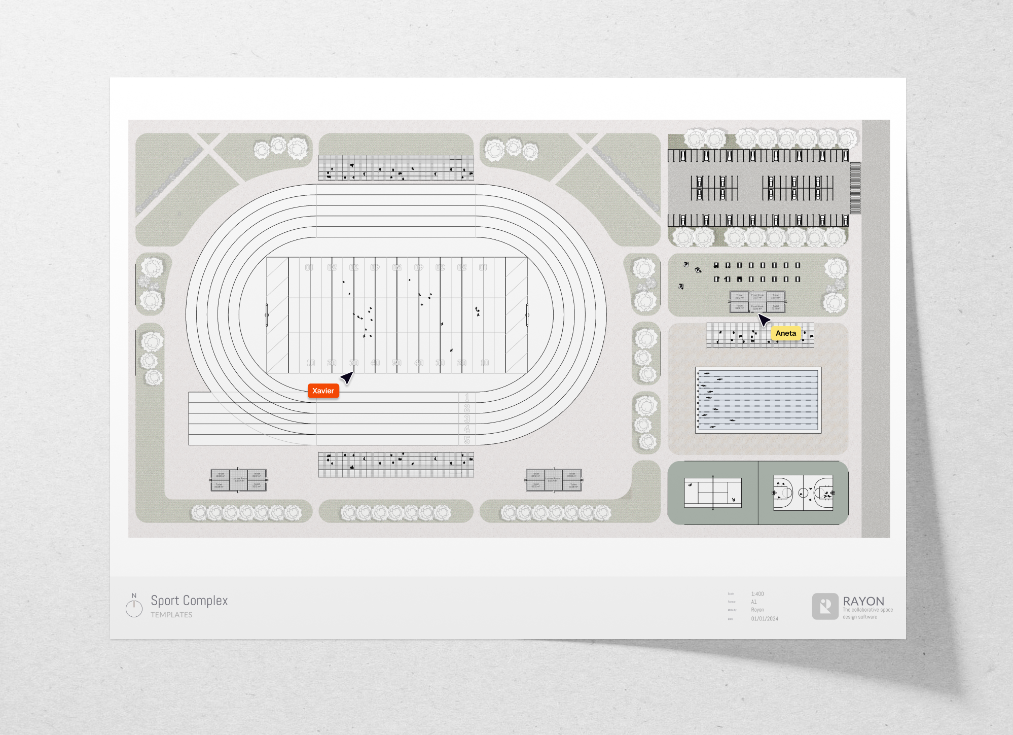
A site plan offers a bird's-eye view of the entire construction site, showing the location of the building in relation to its surroundings, including property lines, roads, utilities, and landscaping. Site plans are typically produced by architects or civil engineers with input from landscape architects.
👉 Get this drawing
Key elements to include in site plans:
- Property boundaries: Exact measurements of lot lines and any easements should be marked clearly.
- Building footprint: The exact positioning of the building in relation to the boundaries, showing distances to property lines and neighboring structures.
- Access points: Driveways, walkways, and other entry points should be indicated, including materials and slope for accessibility.
- Topography: Contour lines indicating the natural slopes, elevations, and any grading required for construction.
- Utilities and services: Location of underground utilities such as water, sewer, gas lines, and electrical conduits. Important for understanding how services will be connected.
- Landscaping: Trees, green areas, retaining walls, and drainage systems. Include information on any zoning requirements for landscaping or green spaces.
- Setbacks and zoning requirements: Ensure compliance with local regulations for building placement.
Design and technical recommendations:
- Ensure all property lines and access points are clearly marked and accurate.
- Include a north arrow for orientation and any topographical features that could affect construction.
2. Floor Plans
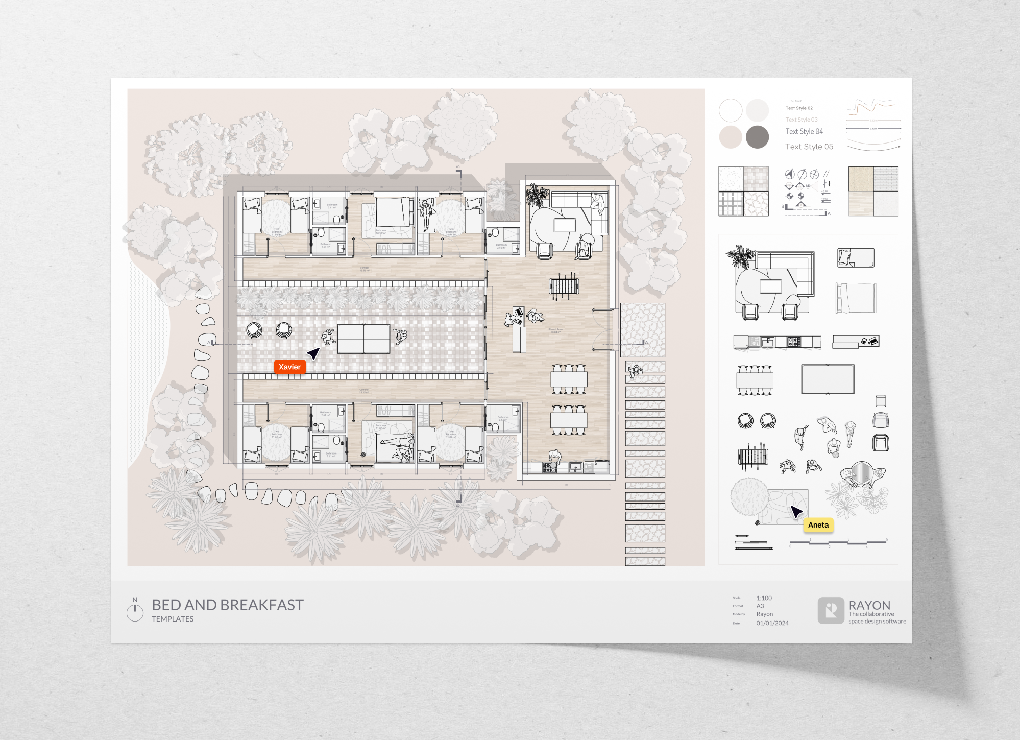
A floor plan is a horizontal cut through a building, showing the layout of spaces, rooms, walls, doors, and windows from an overhead view. It’s essential for visualizing the spatial relationships within the building. Architects typically produce floor plans, but structural engineers and interior designers may also contribute.
👉 Get this drawing
Key elements to include in floor plans:
- Room names and dimensions: Accurate room names (living room, kitchen, bathroom) and dimensions for clear communication with clients and contractors.
- Wall types and materials: Identify different wall types, including load-bearing, partition, and fire-rated walls. Indicate the materials, thickness, and insulation used for each wall type.
- Door and window placements: Clearly marked locations with dimensions, including door swing directions and window elevations. Include details on fire-rated doors or egress windows.
- Furniture layout: Placement of fixed furniture (kitchen cabinets, bathroom vanities) and major movable furniture for space planning.
- Flooring materials: Notes on flooring materials in each room, particularly in areas where transitions between different floor types occur (e.g., hardwood to tile).
- Structural elements: Include columns, beams, or pilasters that are integral to the structural integrity of the building.
- Annotations and comments: Detailed notes explaining material finishes, construction methods, or specific requirements (such as soundproofing between rooms).
Design and technical recommendations:
- Ensure clear circulation between rooms and proper furniture placement for functionality.
- Include annotations for structural elements like load-bearing walls or beams that may not be immediately obvious.
3. Elevations
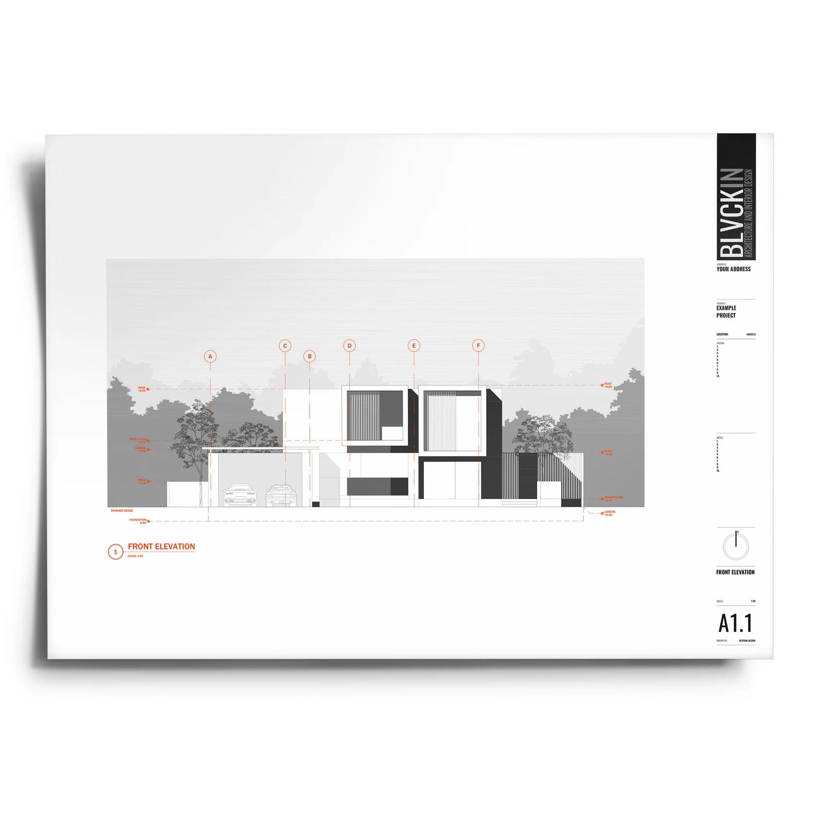
Elevations are flat representations of a building’s exterior or interior walls, showing vertical details like windows, doors, and finishes. Architects create elevations, often with input from structural engineers or interior designers for interior elevations.
Source: Etsy
Key elements to include in elevations:
- Exterior finishes: Materials and textures for walls, roofs, and any cladding systems. Include precise notes on colors and materials to ensure the intended aesthetic is achieved.
- Roof pitches and overhangs: Roof angles and dimensions of eaves, fascia, and soffits. Indicate gutter systems and downspouts for proper drainage.
- Window and door sizes: Dimensioned elevations for all windows and doors, including sill and lintel heights, as well as materials and finishes.
- Vertical connections: How the different floors, walls, and external elements connect.
- External elements: Include details for balconies, terraces, and decks, showing how they integrate with the overall design.
- Waterproofing and drainage: Annotations for waterproofing techniques at wall-roof junctions or areas prone to water ingress, such as balconies or basement walls.
Design and technical recommendations:
- Ensure that materials and finishes are consistent with the overall design intent.
- Check that window placements maximize natural light without compromising structural integrity.
4. Sections
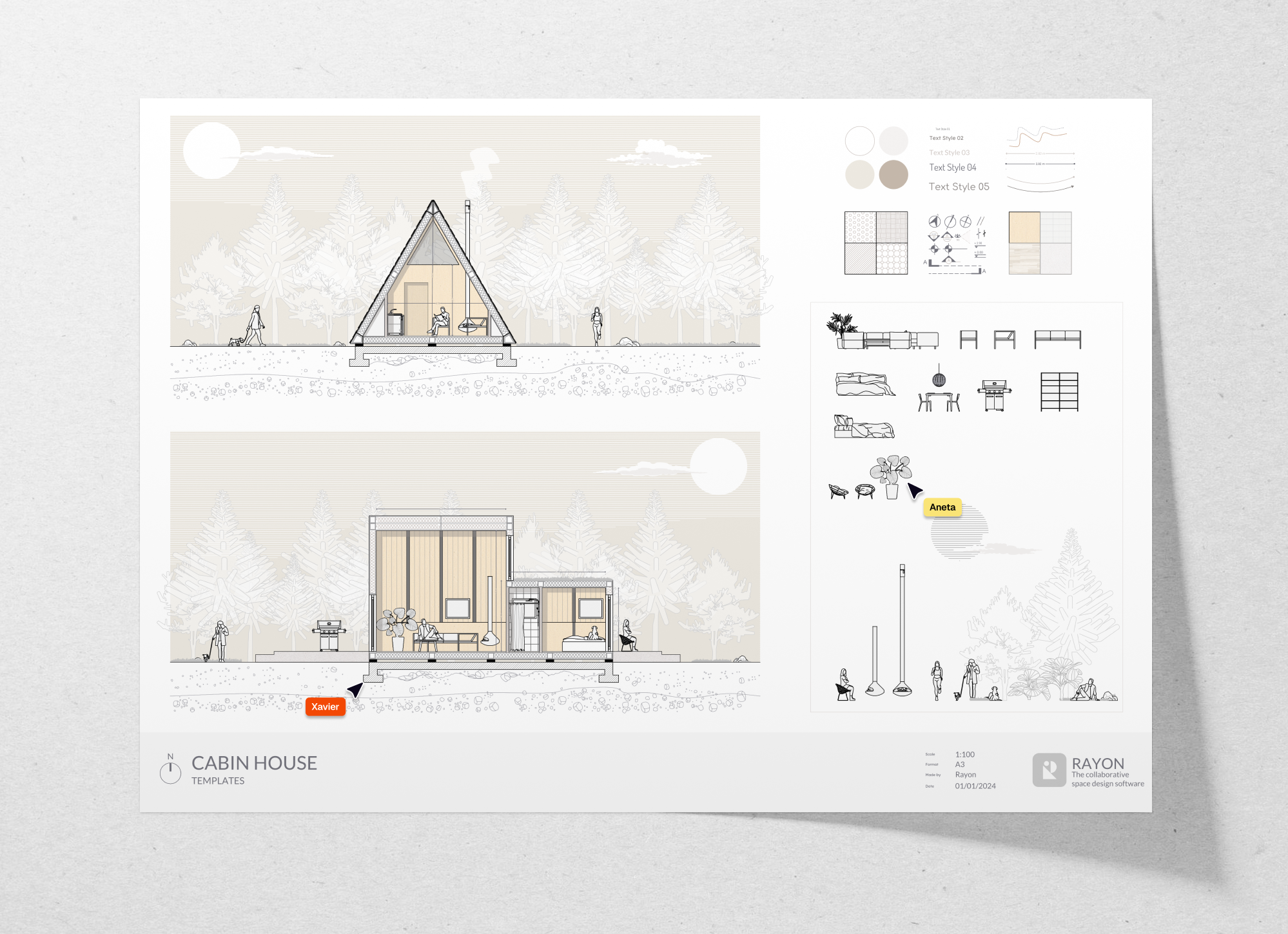
Sections are cross-sectional views that show the interior structure of the building, cutting through walls, floors, and roofs to reveal the construction details at different heights. Architects and structural engineers typically collaborate on sections to ensure accuracy in both design and structure.
👉 Get this drawing
Key elements to include in sections:
- Floor and ceiling heights: Exact dimensions from floor to ceiling and floor-to-floor, including dropped ceiling areas or bulkheads for HVAC systems.
- Wall assemblies: Detailed layers of the wall construction, from exterior cladding through to interior finishes, showing insulation, vapor barriers, and structural components.
- Foundation details: Include depth and type of foundation (e.g., slab, crawl space, basement) and any insulation or waterproofing measures.
- Roof structure: Rafters, trusses, and roof construction details, including the type of insulation and weatherproofing used.
- Connection details: Vertical connection points between different materials, such as the interface between floors, walls, and ceilings.
Design and technical recommendations:
- Ensure that all structural components are correctly dimensioned and detailed.
- Use sections to demonstrate how different materials and elements connect and interact.
5. Structural Drawings
Structural drawings provide the details necessary to build the load-bearing elements of the building, such as foundations, beams, columns, and floors. Structural engineers are responsible for producing these detailed drawings.
Key elements to include in structural drawings:
- Load-bearing elements: Detailed specifications for beams, columns, and load-bearing walls, including materials, sizes, and reinforcement details (e.g., steel beams, concrete columns, or wood studs).
- Foundation systems: Detailed foundation drawings, including pile or footing types, reinforcement schedules, and soil-bearing capacity considerations.
- Connection details: Bolted, welded, or reinforced connections between structural members, with clear annotations for materials and methods.
- Reinforcement schedules: Rebar and mesh placement for concrete elements like foundations and slabs, showing diameter, spacing, and overlap requirements.
- Wind and seismic considerations: If applicable, include details on bracing systems, shear walls, or other reinforcements for lateral loads (wind, seismic events).
Design and technical recommendations:
- Ensure that the structural elements can support the loads they will carry, including wind, seismic activity, and occupancy.
- Double-check that material specifications meet local building codes and safety standards.
6. MEP (Mechanical, Electrical, and Plumbing) Drawings
MEP drawings show the mechanical (HVAC), electrical, and plumbing systems within the building. These are essential for ensuring the building's infrastructure works efficiently. MEP engineers or specialized contractors create these drawings, often in coordination with architects.

👉 Get this drawing
Key elements to include in MEP drawings:
- HVAC systems: Ductwork layout with sizes and material specifications, vent and return air locations, as well as equipment like air handlers or condensers.
- Plumbing layouts: Complete plumbing diagram showing hot/cold water supply, drainage, and venting. Include pipe sizes, fixture locations, and any backflow prevention.
- Electrical wiring: Layout of electrical circuits, outlets, and light switches. Include panelboard locations and wiring for high-demand systems (e.g., kitchen appliances, HVAC).
- Fire protection: If applicable, include fire sprinkler systems or alarm systems, detailing pipe locations and sprinkler head types.
Design and technical recommendations:
- Coordinate between HVAC, electrical, and plumbing systems to avoid clashes.
- Ensure that systems meet energy efficiency standards and local building codes.
7. Shop Drawings
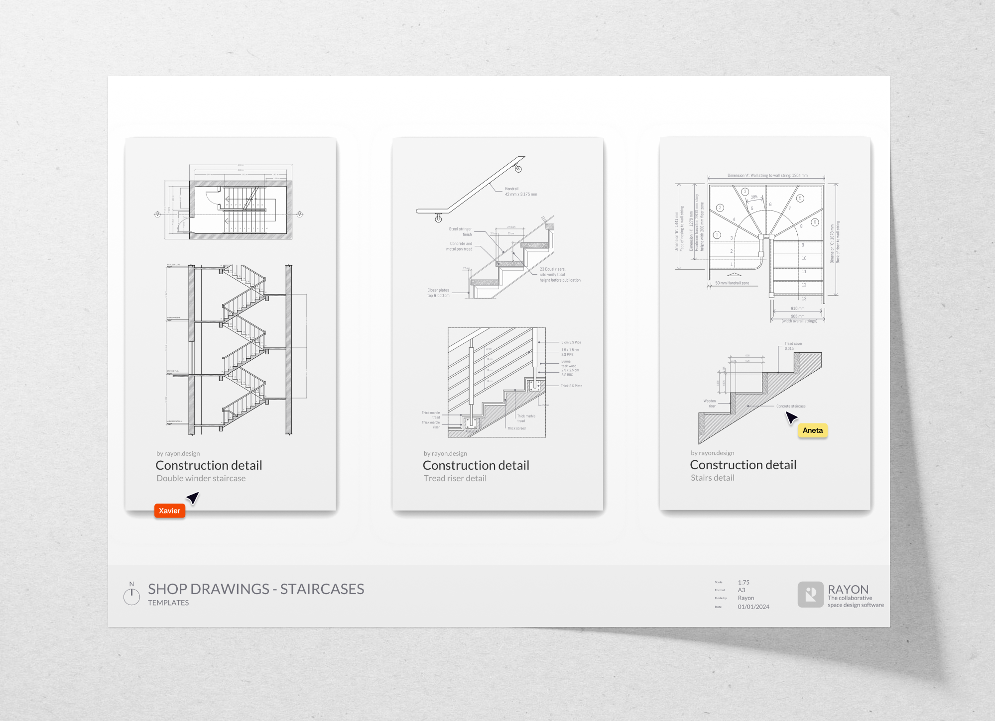
Shop drawings are detailed representations of custom components like cabinetry, metalwork, or prefabricated elements. They are produced by manufacturers or contractors to ensure everything fits correctly on-site. Contractors, manufacturers, or specialized subcontractors are responsible for shop drawings.
👉 Get this drawing
Key elements to include in shop drawings:
- Custom fabrication details: Detailed shop drawings for custom components like cabinetry, stairs, or architectural metalwork. Include precise measurements, assembly methods, and material specifications.
- Component interaction: Show how prefabricated elements integrate with the rest of the structure, particularly where custom tolerances or special installation methods are required.
- Material finishes and tolerances: Include precise specifications for finishes and acceptable tolerances to avoid installation issues.
Design and technical recommendations:
- Double-check dimensions against architectural drawings to avoid on-site errors.
- Ensure that all materials and finishes match the design specifications for aesthetic consistency.
8. Millwork Drawings
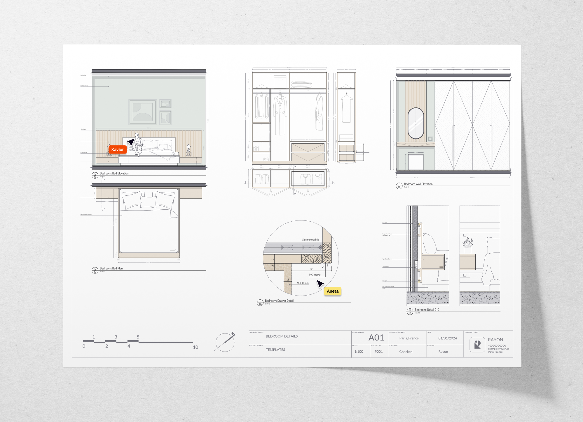
Millwork drawings provide detailed instructions for the fabrication and installation of custom woodwork such as cabinets, moldings, and shelving units. Millwork drawings are produced by millwork contractors or cabinet makers, often in collaboration with architects or interior designers.
👉 Get this drawing
Key elements to include in millwork drawings:
- Joinery details: Detailed drawings of joints for custom woodwork, showing how each element is constructed and assembled.
- Material selections: Specify wood species, veneers, and finishes, including stain or lacquer types, to meet both aesthetic and durability requirements.
- Installation methods: Detailed mounting and fastening systems for built-in cabinetry, including allowances for expansion and contraction of wood.
- Clearances and tolerances: Dimensions for drawers, doors, and shelving with precise clearances to ensure smooth operation and prevent warping.
Design and technical recommendations:
- Ensure that all dimensions are accurate to avoid costly mistakes during fabrication.
- Specify wood types and finishes that match the overall design aesthetic and durability requirements.
9. As-built Drawings
As-built drawings are created after construction is complete to reflect any modifications made during the building process. They represent the final, actual condition of the building. They will then include the different documents we saw before, such as floor plans, elevations, sections. Contractors generally produce as-built drawings, often with input from architects to ensure accuracy.
Key elements to include in as-built drawings:
- Changes during construction: Document all modifications, such as relocated walls, rerouted utilities, or any change in dimensions or materials from the original design.
- Final material placements: Confirm the location of all permanent fixtures, including HVAC systems, electrical outlets, and plumbing connections.
- Hidden systems: Show as-built locations of hidden utilities (pipes, wiring) for future maintenance, repairs, or renovations.
Design and technical recommendations:
- Ensure all changes made during construction are accurately documented.
- Use as-built drawings as a reference for future renovations or repairs.
10. Reflected Ceiling (RC) Plans
RC plans show the ceiling layout, including lighting fixtures, HVAC vents, and other ceiling-mounted elements from a top-down perspective. Architects typically create RC plans, often in collaboration with MEP engineers.
Key elements to include in RC plans:
- Lighting layout: Complete layout for all ceiling-mounted lighting fixtures, including recessed lights, pendants, and chandeliers, along with their exact positions and electrical connections.
- HVAC vents: Placement of ceiling vents for heating and air conditioning, ensuring coordination with other ceiling elements.
- Ceiling finishes: Specify materials for ceiling finishes, including suspended ceilings, acoustic panels, or drywall, along with color and texture.
- Coordination with structural elements: Ensure alignment with structural beams or trusses, which may affect the placement of fixtures or vents.
Design and technical recommendations:
- Ensure that the ceiling plan complements the floor plan, with proper lighting and airflow.
- Coordinate ceiling elements with other systems like HVAC to avoid interference.
Conclusion
Understanding the different types of construction drawings is essential for any architectural or construction project. Each drawing serves a unique purpose, helping to bring the design to life while ensuring that the building is safe, functional, and compliant with regulations.
Rayon is the fastest tool to create perfect construction drawings, from detailed floor plans to reflected ceiling plans.
Our intuitive drawing tools, including wall editing, dimensioning, styles, and an extensive block library, make it easier than ever for architects, engineers, and contractors to create beautiful, precise construction documents.
→ Try Rayon for free